Secondary Controllers
Many EIDE I/O cards support secondary controllers, allowing for up to four ATA devices, as mentioned earlier. Before installing a card, be sure that jumper settings are set properly (see Figure 9.2). Secondary controllers are always set at I/O address 170h and IRQ 15.
Many cards come preset with the secondary controller disabled. Also check the advanced CMOS settings to make sure that any secondary controller enable/disable options are set to enabled.
NOTE
Some EIDE controller cards require that the CMOS options for secondary port hard disk drives be left as "Not Installed." Be sure to read all documentation that comes with these cards.
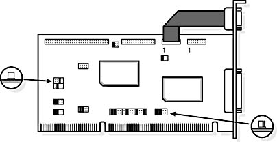
Figure 9.2 Controller card with jumpers
Secondary IDE interface and on-board channels are best suited for use with CD-ROM, DVD, or tape drives. Many secondary controllers on older machines run at a lower PIO mode (0 or 1) than the primary controller (3 or 4). It is always best to check the documentation first.
LBA or CHS?
Most BIOSs can support both LBA and CHS. Enhanced BIOS allows the system to get around the MS-DOS limitation of 528 MB per hard disk and is the easiest way to install an EIDE drive. An enhanced BIOS will support either the Western Digital LBA mode or the Seagate Extended CHS mode.
NOTE
The two translation options are not interchangeable. It is not possible to partition a drive in one computer using one option and move it to a system that uses the other option. Also, see the earlier information about drives of over 8.4-GB capacity. CHS settings are not "real" for drives larger than that size, and they must use some form of controller, system, or third-party software translation to work.
What if a computer does not support either CHS or LBA? Most newer large-capacity drives will provide a disk manager disk, or the ability to make one from the drive itself. (If the information is on the disk, you will be able to access a small MS-DOS partition with the data. The instructions for accessing this data are very specific and must be followed according to the manufacturer's requirements.) This software, when installed properly, performs the same task as CHS or LBA. When using this method, you need to first answer this question: Is the drive in the master or slave position?
- If it is in the slave drive, install the appropriate driver in the CONFIG.SYS file.
- If it is in the master drive, the driver must be loaded before anything else, including the CONFIG.SYS file. This is done by changing the Dynamic Drive Overlay (DDO) in the master boot record. The software provided by the drive manufacturer should make these changes for you.
There are some drawbacks to using this method rather than LBA or CHS:
- Microsoft no longer supports the use of DDO software.
- When booting up from a floppy disk, for the hard disk drive to be accessible, the device must be loaded from the floppy disk's CONFIG.SYS file.
- A virus might attack the master boot record, where this file resides. This can cause some serious problems and at the very least will require reinstallation of the DDO file. Always keep a bootable, virus-free floppy disk on hand.
- The driver that allows use of a large, hard disk drive might also use a large chunk of conventional memory. The tradeoff might not be worth it.
- Many hard disk drive repair programs cannot be used with DDO.
- The software might cause conflicts with the operating system or other drivers.
Setting PIO Mode
There are five PIO modes. A drive must be set properly to achieve the best performance. The following table shows the parameters of PIO modes.
| PIO Mode | Cycle Time in Nanoseconds (ns) | Transfer Rate (MB per second) |
|---|---|---|
| 0 | 600 | 3.3 |
| 1 | 383 | 5.2 |
| 2 | 240 | 8.3 |
| 3 | 180 | 11.1 |
| 4 | 120 | 16.6 |
Answer the following questions before setting the mode:
- What is the fastest mode supported by the hard disk drive?
- What is the fastest mode supported by the controller?
- What is the fastest mode supported by the BIOS or device driver?
CAUTION
The maximum achievable PIO will be limited by the slowest component. Setting a mode that is too fast will not damage the driver, but it might damage your data.
To set up the PIO mode:
- Determine the PIO of the drive. This is preset by the manufacturer and cannot be changed.
- Determine the fastest speed your controller can handle. Most hard disk drives can support PIO mode 2. If you're using an ISA card, PIO mode 2 is the highest PIO available. The two fastest PIO modes, 3 and 4, must be run from either a VL bus (VESA local bus) or a PCI controller. Be careful with on-board controllers! On PCI systems, almost all on-board controllers are PCI; on VESA machines, they are VL bus.
- Set up the BIOS on the CMOS. If auto setup is available, use it.
-
PIO modes 3 and 4 use a hardware flow control called IORDY (I/O ReaDY), also known as IOCHRDY. This setting allows the drive to slow down the data transfer as the head moves across the disk.