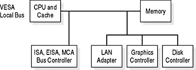
Figure 10.5 VESA local bus design
The speed of the system data bus is based on the clock rate of the motherboard's crystal. During the heyday of the VLB, this was usually 33 MHz, and VLB cards usually ran at half that rate, far outpacing the ISA bus. Some cards ran as fast as 50 MHz, using the full speed of the souped-up system bus. That often caused system crashes, because 50 MHz was outside the VLB specification.
The chip design for the VLB controller was relativity simple, because many of the core instructions were hosted by the ISA circuits already on the motherboard, but the actual data passes were on the same local bus as the one used by the CPU.
The design specification provides two other performance-boosting features: burst mode and bus mastering. In burst mode, VLB devices gain complete control of the external data bus for up to four bus cycles, passing up to 16 bytes (128 bits) of data in a single burst. Bus mastering allows the VLB controller to arbitrate data transfers between the external data bus and up to three VLB devices without assistance from the CPU. This limit of three devices also limited the maximum number of VLB slots to three and called for the use of a coprocessor. Display-system design is covered in more detail in Tutorial 11, "The Display System: Monitors and Adapters."
The actual connectors on the motherboard resemble an ISA slot with an additional short slot aligned with it. On systems that support this interface, one to three slots are located on the side of the motherboard closest to the keyboard connection.