Controlling the flow of communication is called interruption. Every CPU has a wire called the INT wire. If voltage is applied to the wire, the CPU interrupts what it is doing and attends to the device. For example, when a mouse button is pressed, the CPU attends to the interrupt request, invoking the necessary BIOS routine to query the mouse.
Because the CPU has only one interrupt wire and must handle many peripheral devices, a specific type of chip, called the 8259 chip, is present on the system to help the CPU detect which device is asking for attention. Every device that needs to interrupt the CPU is provided with a wire called an IRQ (interrupt request). If a device needs to interrupt the CPU, it goes through the following steps:
- The device applies voltage to the 8259 chip through its IRQ wire.
- The 8259 chip informs the CPU, by means of the INT wire, that an interrupt is pending.
- The CPU uses a wire called an INTA (interrupt acknowledge) to signal the 8259 chip to send a pattern of 1s and 0s on the external data bus. This information conveys to the CPU which device is interrupting.
- The CPU knows which BIOS to run.
The 8088 computers used only one 8259 chip (see Figure 10.8), which limited these computers to using only eight available IRQs. Because a keyboard and system timer were fixtures on all computers, these IRQs were permanently wired into the motherboard. The remaining six wires were then made part of the expansion bus and were available for use by other devices.
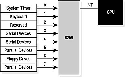
Figure 10.8 8259 chip with IRQ assignments
Starting with the generation of computers based on the 286 chip, two 8259 chips were used to add eight more available IRQs (see Figure 10.9). These new wires were run to the extension on the 16-bit ISA expansion slot (the 8-bit XT slot was extended to a 16-bit XT slot). Because the CPU has only one IRQ wire, one of the IRQs is used to cascade the two 8259 chips together. This gives a total of 15 available IRQs.
NOTE
When a device is cascaded, this means that data is passed through a common path between two devices, usually on to another destination. The term denotes a situation much like water cascading over a waterfall on its journey to the sea.
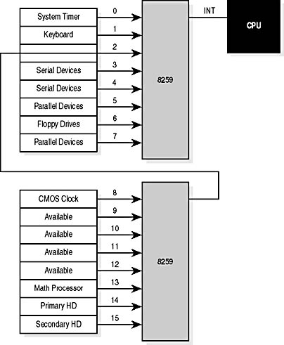
Figure 10.9 Cascading 8259 chips
Notice that the cascade removes IRQ 2. IRQ 9 is directed to the old IRQ 2 wire. Any older device designed to run on IRQ 2 will now run on IRQ 9. Some important facts to remember about IRQs include the following:
- IRQ 2 and IRQ 9 are the same IRQ.
- Three IRQs are hardwired (0-system timer, 1-keyboard controller, and 8-real-time clock).
- Four IRQ assignments are so common that no computer or device manufacturer dares to change them for fear their devices will cause conflicts (6-floppy disk controller, 13-math coprocessor, 14-primary IDE controller, and 15-secondary IDE controller).
- Four IRQs default to specific types of devices but can be changed: IRQ 3-COM2 and COM4, 4-COM1 and COM3, 5-LPT2, and 7-LPT1. (See table that follows.)
- The rest (IRQs 2/9, 10, 11, and 12) are not specific and are available for use.
NOTE
The 8259 chips no longer exist on a motherboard. Their functions have become part of the multifunction chips called chip sets that perform all the functions of the 8259 chips and more. However, the information provided in the preceding section is still useful for understanding how this portion of the chip set operates. Also, the IRQ assignments generally are the same.
The following table provides typical IRQ assignments.
| IRQ | Function | Available for Change |
|---|---|---|
| IRQ 0 | System timer | No |
| IRQ 1 | Keyboard controller | No |
| IRQ 2/9 | Available | Yes |
| IRQ 3 | COM2, COM4 | Usually |
| IRQ 4 | COM1, COM3 | Usually |
| IRQ 5 | LPT2 | Usually |
| IRQ 6 | Floppy disk controller | No |
| IRQ 7 | LPT1 | Usually |
| IRQ 8 | Real-time clock | No |
| IRQ 10 | Available | Yes |
| IRQ 11 | SCSI/available | Yes |
| IRQ 12 | Available | Yes |
| IRQ 13 | Math coprocessor | If there is no math coprocessor |
| IRQ 14 | Primary IDE controller | No |
| IRQ 15 | Secondary IDE controller | Usually |
Setting IRQs
Devices lacking a fixed or standard IRQ (except for newer PCI cards in compatible PCs) must have their IRQs set during installation. Read the accompanying manuals to learn about these. Setting IRQs is one of the first topics discussed in any device's installation instructions. The manual will tell you not only how to set the IRQ, but also the limits, if any, of the device.
Just like I/O addresses, IRQs can be set using hardware, software, or a combination of both. The best way to ensure that no two devices share the same IRQ is to document the IRQs for each device you install in a computer and file that documentation in a location in which you can find it easily if it is needed. As an example, suppose one of your customers has recently installed a sound card that now locks up when a parallel-port tape backup unit is used on the system. This strongly indicates an IRQ conflict. You need merely to check the sound card and the tape backup IRQ settings you have on file and change one if necessary.
IMPORTANT
Some devices have a limited number of IRQ settings; you might need to change the IRQs of other devices in order to free one of these IRQs.