Modem Basics
A modem is a peripheral device that enables computers to communicate with each other over conventional telephone lines, ISDN cable lines, or even without wires. The word modem comes from combining the words MOdulator and DEModulator. In radio parlance, to modulate a signal is to change the frequency (FM) or amplitude (AM) of a carrier (fixed signal) by superimposing a code (voice or other information) on top of the signal. The reverse is to demodulate, to remove the fixed signal and have the superimposed code remain. For many years, this has been an effective way to communicate over long distances, using both wires and radio waves.
The following table defines some basic terms used with modem communication.
| Term | Definition |
|---|---|
| Baud rate | The number of events, or signal changes, that occur in one second. It was used as an early measurement of how fast a modem can send data, because at that time, modems transmitted data at a speed equal to the baud rate (one bit per cycle). Today's high-speed modems use complex signals to send more data; therefore, data transfer can exceed baud rate. The baud rate is limited by the capability of copper wires to transmit signals. |
| bps | Stands for bits per second-the speed at which a modem transmits data. Typical rates are 14,400; 28,800; 33,600; and 56,600 bps. These numbers represent the actual number of data bits that can be transmitted per second. |
| Browser | Software used to explore sites on the World Wide Web using the HyperText Transfer Protocol (HTTP). |
| Bulletin board service (BBS) | Interactive software that offers the ability log directly onto a remote computer to post and retrieve messages, and to upload and download files. Some BBSs offer the opportunity to chat live with other members who are online at the same time. The Internet has diminished the importance of BBS software. |
| Download | The act of transferring a file from a remote computer (host) to a local computer (client). When downloading, you are receiving a file. |
| DTMF | Stands for dual-tone multifrequency, the technology behind the tones of a touchtone phone. |
| Internet | A worldwide, online network that links computers by means of the TCP/IP protocol. (See entry for TCP/IP later in this table.) |
| Internet server | A computer/software combination that provides a gateway and supporting services for linking other computers to the Internet. |
| IP | Stands for Internet Protocol-the network protocols used to define how data is transmitted on the Internet. |
| IP address | Stands for Internet Protocol address-a unique, 32-bit address that identifies every network and host on the Internet. (A host is the TCP/IP network interface within the computer, not the computer itself; a computer with more than one network interface card-NIC-can have more than one IP address, one for each card.) |
| ISDN | Stands for Integrated Services Digital Network, a digital telephone connection like a modem that uses digital links and offers speeds about five times that of an analog modem. The ISDN system is a packet system that can also handle voice communication. |
| ISP | Stands for Internet service provider-a host computer that you can dial into over a modem to connect to the Internet. |
| Logging on | The process of sending the appropriate signals and gaining access to a remote computer over a modem or other remote connection. |
| Modem | A device for converting a computer's digital data stream to and from an analog form so that it can be sent over a telephone line. |
| Offline | Status of a computer that is not connected to another device over a modem or other telecommunications device. |
| Offline reader | A program designed to display e-mail messages or other information that has been downloaded to one computer from another. |
| Online | An active connection between two computers, making possible the exchange of data. |
| POTS | Stands for Plain Old Telephone Service, a common term that denotes the basic analog phone network as compared to newer digital networks used for packet transfer of data. |
| Protocol | A set of rules that govern the transfer and verification of data between two or more systems. |
| Proxy server | A computer/modem/software combination that manages Internet traffic to and from a local area network (LAN) and can provide other features, such as document caching and access control. |
| Settings (modem) | Configuration required by the telecommunications software in order for data to be transmitted. Usually 8 bits, no parity, 1 stop bit (8N1) will work. Some BBSs require special terminal emulation, a software configuration that mimics the operation of proprietary mainframe terminals like the VT100. |
| Sysop | The system operator of a BBS (pronounced SIS-op). |
| TCP/IP | Stands for Transmission Control Protocol/Internet Protocol-the name given to a collection of protocols that were designed in the 1970s for use on the large-scale, mixed-platform environment that became the Internet. |
| Telecommunications | The ability to transmit data over telephone lines to a remote computer. Often abbreviated as "telecom." |
| Telecommunications software | An application that allows two computers to communicate with each other. Both computers must use compatible software for communication to take place. |
| Upload | The ability to transfer a file from a local computer to a remote computer. When uploading, you are sending a file to another computer. |
| Webmaster | A person who manages a Web site on the Internet's World Wide Web. The Webmaster's duties are analogous to those of a BBS. |
Communication
Two basic problems arise from using modems to transmit data. The first problem is that, as we saw in Tutorial 4, computers transfer data using 8, 16, or 32 parallel wires or buses, while telephone systems use only two wires. (See Figure 12.4)

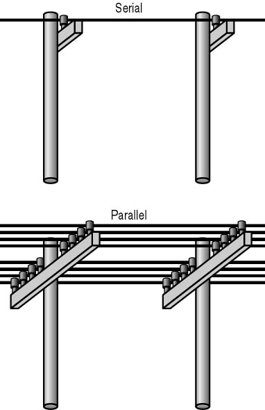
Figure 12.4 Serial and parallel communication
The second problem is that telephone and radio systems use analog signals (based on waveforms), and computers use digital signals, either on or off, as shown in Figure 12.5.

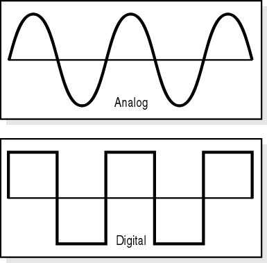
Figure 12.5 Analog and digital signals
A modem resolves both of these problems by acting as an analog-to-digital (A/D) converter as well as a modulator/demodulator.
Serial/Parallel Conversion
Virtually all personal computers use a family of chips produced by National Semiconductor to run serial ports. Known as UARTs (universal asynchronous receiver-transmitters), these chips convert an 8-bit wide parallel data path to a 1-bit wide serial path.
The UART has gone through several major changes during the PC era, and there are many different types of UARTs with different functions. The following table lists several of the more common ones.
| Chip | Description |
|---|---|
| INS8250 | The original chip used in the IBM PC, the INS8250 operated at speeds up to 56 kilobits per second (Kbps). The 8250A and 8250B incorporated fixes for minor bugs in the original design, but the 8250 series was unreliable at speeds over 9600 bps. |
| 16450 | Designed for 286-based PCs, the 16450 is the first UART that reliably operated at 9600 bps and above. |
| 16550 | The 16550 allowed use of more than one DMA channel to achieve improved throughput over the 16450. |
| 16550A | An improved version of the 16550, the 16550A is the only UART installed on today's computers. It adds support for First in-First Out (FIFO) communication. This is the only UART that should be installed in current PCs or add-on cards that are used to provide expansion card-based COM ports. |
Determining which UART chip is installed in a computer can be easily accomplished by using the MSD (Microsoft Diagnostics) utility that comes with MS-DOS, Windows 3.x, and Windows 95 and Windows 98 (Windows Device Manager). Select COM Ports from the MSD main menu. (See Figure 12.6.)

Figure 12.6 MSD utility-COM ports
Digital Communication
The movement of data from one computer to another over telephone lines is a multistep process. The first step is to convert the data from parallel to serial form. Then the digital information must be broken into uniquely marked packets (this allows the receiving computer to distinguish one byte from another).
Asynchronous Communication
Asynchronous communication is any data transmission that does not link the two devices with a common data clock. This is useful because the length of time between sending a packet and its receipt on the other end can vary between the communicating devices. A signal called a start bit is sent at the beginning of each segment, and a signal called a stop bit is sent at the end. These let the receiving device note the boundaries (beginning and end) of a transmission packet. Early PC modems were almost always asynchronous devices operating at speeds of no more than 18,000 bits per second.
Synchronous Communication
Synchronous communication sends data blocks at strictly timed intervals that are monitored at both ends. Modems operating at speeds up to 56 Kbps over standard telephone audio lines are usually synchronous devices.
Many protocols are used for PC-to-PC modem communication. Kermit, Xmodem, Ymodem, and Zmodem are four common ones. The following is a summary of how these protocols work:
- Before a modem sends any data, a communication link must be established. To do this, the modem sends a series of standardized bytes-called sync bytes-to the device it is to communicate with.
- The modem on the other end receives the sync bytes.
- The receiving modem perceives that it is receiving sync-byte data and synchronizes with the incoming data.
- After sending the sync bytes, the sending modem adds a start-of-text (STX) character.
- The data bytes are sent. The data in synchronous transmission is processed in packets or in blocks of fixed length, depending on the protocol used.
- Each packet ends with an end-of-text (ETX) character and two error-checking characters called CRC (cyclical redundancy check) characters or BCCs (block check characters).
- The receiver then responds with an ACK-acknowledgment character-if the data is good, or a NAK-negative acknowledgment-if transmission errors have occurred.
NOTE
In asynchronous communication, the receiving modem does not respond-it just reads the data and acts on it-unless a timing error is reported. In synchronous modes the receiving modem must respond.
Parity
Asynchronous communication packets have an optional parity bit that is used for error detection. The parity bit is used by the receiving port to verify whether the data is intact or has been corrupted. There are two types of parity:
- Even parity: The sending computer counts the 1s in the data part of the packet; if the number of 1s is even, the parity bit is 0-this makes the total number of bits even. If the number of 1s in the data part of the packet is odd, the parity bit is set to 1-again making the total number of bits even. The receiving port counts the data bits and compares its answer to the parity bit. If the two fail to match, an error is reported, and a request to retransmit the packet is passed to the sending computer.
- Odd parity: This works in exactly the same way as even parity, except that the total number of bits must be odd.
The use of parity bits is optional. The quality of data transmission and telephone lines has improved to the extent that parity bits are no longer required. However, if data accuracy is critical and/or telephone-line quality is questionable, use parity.
Hardware
Now that we've seen how modems send and receive data, we examine the hardware involved.
Internal Modems
The entire modem and even its serial port can be accommodated on a single expansion card. This configuration offers lower cost than that of an external modem, but is more prone to compatibility problems with either the on-board UART or the COM port IRQs.
USB Modems
Most new PCs offer two universal serial bus (USB) ports, either of which can be used to attach a modem. USB is a hot swap (the device can be added or removed without powering down the PC), Plug and Play interface (See Tutorial 10, "Expansion Buses,") well suited to this task. To install a modem this way, usually all that is required is to attach a USB cable between the modem and PC, connect the phone-line cable between the modem and a wall jack, and load the modem-driver software from the manufacturer's configuration disk when prompted.
External Analog Modems
The original modems used a pair of cups to cradle a telephone handset over a built-in speaker and microphone; in this way, the modem would send and receive tones acoustically, and the telephone handset would relay the tones. Today, the external modem is usually a rectangular box with a row of status lights on the front, a speaker to give audible feedback, and a number of ports on the back. Two of those ports are telephone jacks-one to connect to the wall line and the other to pass the telephone signal to a phone for regular voice conversations when the modem is not in data mode. A third port on the back of the modem is a serial port using a standard 25-pin RS-232 connector that passes data to and from a serial port on the PC.
ISDN Terminal Adapters
Until about 30 years ago, the North American telephone network was an analog system connecting phones by means of a grid of copper wires. Today, the long line sections (intercity telecom lines) are part of a packet-based, digital switching system, but the final run from the local switch to most homes is the aged copper-wire POTS line.
ISDN is an all-digital phone connection that uses special high-quality phone lines to ensure clean, high-speed, data transfers-directly to the user's home or business. Both voice and data are carried by bearer channels (B channels) with a maximum speed per channel of 64 Kbps. A companion data channel (D channel) handles signaling at 16 Kbps (or 64 Kbps, depending on service provided by the carrier).
NOTE
In the context of ISDN communications, "K" means 1000; in other computing contexts, "K" means 1024.
ISDN connections do not make use of a modem. Instead, a device called a terminal adapter (TA) serves as the interface for both computers and analog phones served in a location. Most small-business and residential customers make use of a TA that has a 25-pin serial connection to attach to a computer serial port and that also provides analog telephone connections for two lines.
ISDN is complicated to install and should be set up using the help of a vendor or the local telephone company. After installation, ISDN functions like a high-speed modem, offering not only faster data transfers, but faster connections to remote ISDN providers such as ISPs. Because each TA unit is completely digital, there is no testing of the nature of the remote source by the hardware to establish the maximum connection rate (as with a modem), and links are typically established in under three seconds.
The RS-232 port
External modems and TAs communicate with their host computers by means of an RS-232 communications port. The RS-232 standard was developed by the Electronics Industry Association (EIA) for low-speed data communication; the standard defines a series of signals that are sent between two telecommunications devices to indicate line and transmission status. The following table shows the most common signals.
| Signal | Definition |
|---|---|
| CTS | Clear to Send |
| DCD | Data Carrier Detected |
| DSR | Data Set Ready |
| DTR | Data Terminal Ready |
| RI | Ring Indicator |
| RTS | Request to Send |
| RTSRD | Request to Send/Receive Data |
RS-232 Cables
RS-232 connections can make use of either 25-pin or 9-pin connectors. On many PCs, the end attaching to a modem or TA has a 25-pin connector, while the PC has a 9-pin connector. The following table presents the layout and signals for both.
| Description | Pin Outs on 9-Pin Cable | Pin Outs on 25-Pin Cable | Signal | Direction |
|---|---|---|---|---|
| Protective Ground | - | 1 | - | - |
| Transmitted Data | 3 | 2 | TD | DTE ->DCE |
| Received Data | 2 | 3 | RD | DCE ->DTE |
| Request to Send | 7 | 4 | RTS | DTE ->DCE |
| Clear to Send | 8 | 5 | CTS | DCE ->DTE |
| Data Set Ready | 6 | 6 | DSR | DCE ->DTE |
| Signal Ground (Common) | 5 | 7 | - | - |
| Data Carrier Detected | 1 | 8 | DCD | DCE ->DTE |
| Data Terminal Ready | 4 | 20 | DTR | DTE ->DCE |
| Ring Indicator | 9 | 22 | RI | DCE ->DTE |
| Data Signal Rate Detector | - | 23 | DSRD | DCE<->DTE |
Telephone-Line Basics For Modems
Modem connections to the telephone service are made using two wires (ring and tip) that are used in a standard telephone jack. The wires are named for the plug wires used in the original telephone lines by which telephone operators would manually connect two telephones at the phone company switchboard. There are two versions of the telephone jack:
- Half-duplex: The RJ-11 has only two wires, which make up one line. Therefore, only one signal can be sent or received at a time.
- Full-duplex: The RJ-12 uses four wires to make up two lines; it can be used to simultaneously send and receive.
Multifunction Modems
Most modems offer some form of fax capability, along with software that adds functions beyond the average, small, stand-alone fax machine. Such a modem is usually labeled a fax/modem. They can store faxes, both incoming and outgoing, for reference or online reading. Most allow direct faxing of a document from a word processor, generally by using the print command to send the pages to the modem, where they are converted on the fly to the bitmap form used to send and receive fax transmissions. Many programs let you to automatically attach a predesigned cover sheet with each fax.
Another addition to the basic data out/data in modem is voice mail. Here, the PC and telephone work just like an answering machine. If the phone rings and the modem does not detect either a data or fax tone, it switches modes and streams a recorded message (the outgoing message). The caller can be prompted to record a message for the owner, and in some cases the modem will even forward a pager call or fax with the message contents.