NOTE
Find out if the client is having any problems with flickering lights, intermittent problems with other appliances, or is using a power strip with too many connections for the rated use; improper loading of the circuit, not the PC itself, can be the problem.
A bad power supply can cause intermittent lockups and unexpected computer reboots. Erratic problems encountered during booting and changed or erased CMOS information can also be traced to a failing power supply. Bad power supplies have been known to destroy data on mass-storage devices. There are two types of tests for power supplies: a basic test used to verify voltages and an advanced test for checking its internal components.
Basic Voltage Test
The only purpose of this test is to verify the existence and value of voltages. With time, most power supplies show their age by a reduction in voltage. This voltage drop will show itself in both the 5-volt and the 12-volt outputs, but is more pronounced on the 12-volt side.
Prepare the Meter for the Test
Again, meter preparation is quite simple:
- Connect the black lead to the common (-) connector and the red lead to the voltage (+) connector.
- Turn the test selector to DC volts. If the meter has an AC/DC switch, be sure it is set to DC. If the meter does "auto range," set the range to 15-to-20 volts.
Testing the Voltages
The best place to check voltage is at the power supply's P8/P9 or ATX power connectors (see Tutorial 5, "Supplying Power to a Computer"). For P8/P9 systems use the instructions below:
- Place the meter's black (ground) lead on the black wire connection and its red (positive) lead on the yellow (+12 volt) connection.
- Record the voltages. A good power supply will provide a voltage between 11 and 13 volts DC.
- Replace the power supply if the voltage reading is less than 10.
NOTE
Be sure to reverse the leads when using an analog meter to check negative voltages. This is not necessary with a digital meter because it will simply show a negative sign with the reading.
When No Voltage Is Present
If you have completed the basic voltage test and no voltage is present, the problem may not be the power supply. It might, instead, be caused by an excessive load on the system due to another piece of hardware. To determine if that is the case, try the following procedure.
Isolating the Problem
First you should test the hardware:
- Disconnect the Molex leads from the power supply.
- Connect the meter leads as described in the previous sections.
- Turn off the AC power.
- Disconnect all the Molex plugs from the devices.
- Turn the power back on. If power is present at the motherboard, one of the devices is bad and is causing a drain on the power supply.
- Reconnect each Molex plug, one at a time, and test the power. When the power drops out, you have located the offending device.
Advanced Testing
The basic test is designed to quickly isolate the power supply as a problem. In most cases, if the test proves the power supply to be defective, it may be more cost-effective to replace the power supply than to try to repair it. Advanced testing requires a working knowledge of power supplies and removal of the power supply and its cover.
There are three sections to a power supply: the switching network, the transformer, and the voltage regulator (see Figure 13.6).
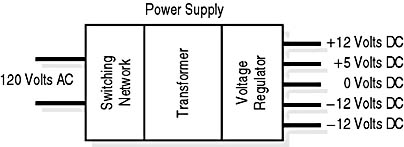
Figure 13.6 Power supply
The Switching Network
AC power coming from the power company is imperfect. It is not uncommon to have sudden increases in voltage called spikes or decreases in voltage called sags (see Tutorial 5, "Supplying Power to a Computer").
To smooth out the power sent to the electronic components, a PC has basic line conditioning capability-a switching network. The better the power supply, the more sophisticated the network. The main components found in a switching network are a fuse, capacitors, rectifiers, and switching transistors (see Figure 13.7).
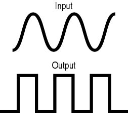
Figure 13.7 Switching network
The switching network performs the following three tasks:
- Filters electrical noise (spikes, sags).
- Eliminates frequency changes (ensuring that current stays at a constant 60 cycles).
- Converts AC sine wave signals to AC square wave signals.
The Transformer
The transformer reduces the voltage of the square wave DC into separate 12-volt and 5-volt square wave AC circuits (see Figure 13.8).

Figure 13.8 Transformer voltage
The Voltage Regulator
The voltage regulator receives the low-voltage AC outputs of the transformer and converts them to clean DC power. The main components in this section are rectifiers, capacitors, and coils.
The voltage regulator section performs three functions:
- It uses rectifiers (diodes) to convert the square wave AC output of the transformer into DC output (see Figure 13.9).
- It regulates the voltage to a constant output level and uses capacitors to remove any ripples that are present.
- It monitors the amount of current used by the computer circuits and adjusts the switching network using a special circuit called the feedback circuit. This compensates for variations in load on the power supply.
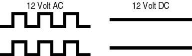
Figure 13.9 Regulator section voltage
CAUTION
Do not open the power supply while it is plugged in, and do not open the power supply until it has been discharged. The power supply can carry dangerous levels of power even when disconnected. Only a properly trained technician should ever open a PC power supply. Given the cost of a power supply, there is no good reason to disassemble one; defective units should be replaced.