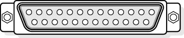
Figure 12.8 Standard 25-pin D connector
The original parallel port was designed only to send information to printers and was unidirectional. However, some bidirectional communication was possible by manipulating the handshaking lines. Today, computer manufacturers have developed updated versions that allow better bidirectional communication while maintaining the original Centronics specification. The Institute of Electrical and Electronic Engineers (IEEE, pronounced "I triple E") developed a standard-IEEE 1284-to oversee the standardization of these ports.
There are three bidirectional standards used today:
- Bi-Tronics: This modified Centronics connection was created by Hewlett-Packard. It utilizes bidirectional communication, allowing the printer to send messages to the computer (out of paper, paper jam, and so forth).
- EPP (enhanced parallel port): This features 2 MB per second data transfer rates, bidirectional 8-bit operation, and addressing to support multiple (daisy-chained) peripherals on a single computer.
- ECP (extended capabilities port): This was developed by Hewlett-Packard and Microsoft. It features 2 MB per second data transfer and bidirectional 8-bit operation. ECP will specify whether transmitted information consists of data or commands for the peripheral. ECP supports CD-ROM and scanner connections, RLE (Run Length Encoded) data compression, and DMA support to increase transfer speed and reduce processor overhead.
NOTE
The EPP and ECP standards often have to be enabled in the CMOS setup before the specified port can use them.
IEEE 1284 Printer Modes
A vast array of printers is available, and in order to ensure that you are obtaining optimum performance, the printer, the printer driver, and the software using the printer must be configured for the same mode. The following table describes various printing modes and their capabilities.
| Mode | Capabilities | Speed | Notes |
|---|---|---|---|
| Compatibility | 8-bit output. Hardware handshaking. No DMA. |
100-200-KB per second out | Original parallel port |
| 4-bit | 4-bit input using some of the printer's handshaking lines. | 100-200 KB per second out; 40-60 KB per second in | HP Bi-Tronics mode |
| 8-bit | 8-bit I/O bidirectional. | 80-300 KB per second | Original bidirectional port |
| ECP | 8-bit I/O. Can use DMA. |
>2 MB per second | Scanners and high-speed printers |
| EPP | 8-bit I/O. | Up to 2 MB per second | Very flexible modes of operation |
Parallel Pin Assignments
Just like modem cables, it is important for printer cables to have the correct pin connections. The following table describes the standard parallel pin assignments for the computer-end (25-pin) and the printer-end (Centronics) connectors.
| Computer | Direction of Data Flow | Printer | Name | ID | Function |
|---|---|---|---|---|---|
| 1 | 1 | Strobe | STROBE | Sends data to printer. | |
| 2 | 2 | Data bit 0 | DBO | ||
| 3 | 3 | Data bit 1 | DB1 | ||
| 4 | 4 | Data bit 2 | DB2 | ||
| 5 | 5 | Data bit 3 | DB3 | ||
| 6 | 6 | Data bit 4 | DB4 | ||
| 7 | 7 | Data bit 5 | DB5 | ||
| 8 | 8 | Data bit 6 | DB6 | ||
| 9 | 9 | Data bit 7 | DB7 | ||
| 10 | 10 | Acknowledge | ACK | Printer acknowledges receipt of data. | |
| 11 | 11 | Printer busy | BUSY | ||
| 12 | 12 | Paper error | PE | ||
| 13 | 13 | Select | SLCT | Indicates printer is online. | |
| 14 | 14 | Auto feed | AUTOFD | ||
| 15 | 32 | error | ERROR | ||
| 16 | 31 | Reset | Printer | INIT | |
| 17 | 36 | Select input | SLECT IN | ||
| - | 18 | 5v | 5 volts available from some printers. | ||
| 18-25 | 16, 19-30, 33 | Ground | Sometimes to pin 17. |