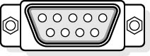
Figure 12.9 Standard 9-pin D connector
The following table describes the pin connection for the 9-pin and 25-pin serial cable connectors.
| 9-pin | 25-pin | Name | ID | Function |
|---|---|---|---|---|
| 1 | Shield | |||
| 3 | 2 | Transmitted Data | TX | Data sent from computer. |
| 2 | 3 | Receive Data | RX | Data sent to computer. |
| 7 | 4 | Request to Send | RTS | Computer is ready to send. |
| 8 | 5 | Clear to Send | CTS | "Other end" is ready to receive |
| 6 | 6 | Data Set Ready | DSR | "Other end" is ready to receive. |
| 5 | 7 | Signal Ground | SG | GND. |
| 1 | 8 | Data Carrier Detected | DCD | The modem has detected a signal from another modem. |
| 4 | 20 | Data Terminal Ready | DTR | Computer is ready to send. |
| 9 | 22 | Ring Indicator | RI | Modem detects line ringing. |
Null-Modem Cables
Null-modem cables are used to directly connect two computers together without the need for a modem. The transmit and receive wires in the cable (wires 2 and 3) are switched to make the computers "think" they are using modems.
SCSI Cables
SCSI cables come in a variety of sizes depending on the type of SCSI used and the manufacturer of the device. Typically, internal cables are flat ribbon types and external cables are shielded bundles.
SCSI Cables
SCSI cables come in a variety of sizes depending on the type of SCSI used and the manufacturer of the device. Typically, internal cables are flat ribbon types and external cables are shielded bundles.
Keyboard Cables
Another peripheral device with a cable that we encounter and yet never think about is the keyboard. Because there are different types of keyboard cables (and connectors) and because, on occasion, the technician might encounter a problem with a keyboard connector, they are worthy of mention.
Keyboards are manufactured in two different styles with different cables and connectors. Earlier versions used a 5-pin DIN connector (DIN stands for Deutsche Industrie Norm, the German national standards organization), and most new keyboards use a 6-pin DIN connector, the same as is used on a PS/2 mouse. Connectors are available to convert the 5-pin DIN to a 6-pin mini-DIN. Although they have a different number of pins, they use the same wires and pin outs. Data is sent serially to the keyboard using the keyboard interface. Data is written to the controller's input buffer to accomplish this. Keyboard data passes through pin 2 of the connector, while clocking signals move through pin 1. A keyboard reset, which can be connected to the system's reset line, is included at pin 3. Ground and +5-volt DC connections are applied to the keyboard through pins 4 and 5.