Points to remember:
- Hold Middle Mouse Button and move the mouse to orbit.
- Hold Middle Mouse Button + Shift key and move the mouse to pan.
- In the sketch mode, if any command or tool is selected, press Middle Mouse Button to deselect it.
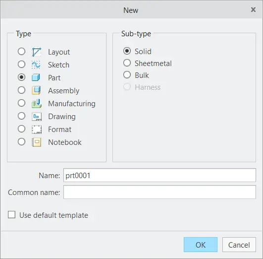
Open creo, click New to make a new file. Change type to Part and uncheck the “Use Default Template”. If we do not uncheck it, the default units would be in inches. We want our units to be millimeters. Click “OK”.
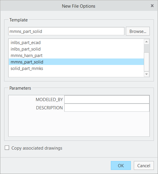
In the next step, click “mmns_part_solid”, our units would be in millimeters.
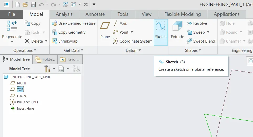
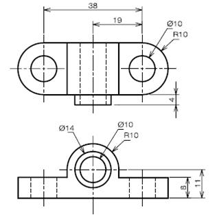
We are following the drawing that was shown earlier, we are going to make the top view, so click on the “TOP” plane from model tree as shown and then click on the sketch option.
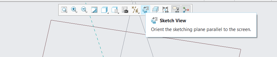
Once you are in the sketch tab. click Sketch View, this will orient the view.
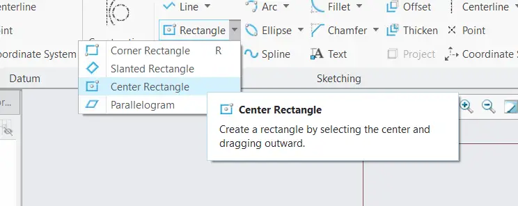
From above click Center Rectangle, a center rectangle has equal distance from the center to its four corners.
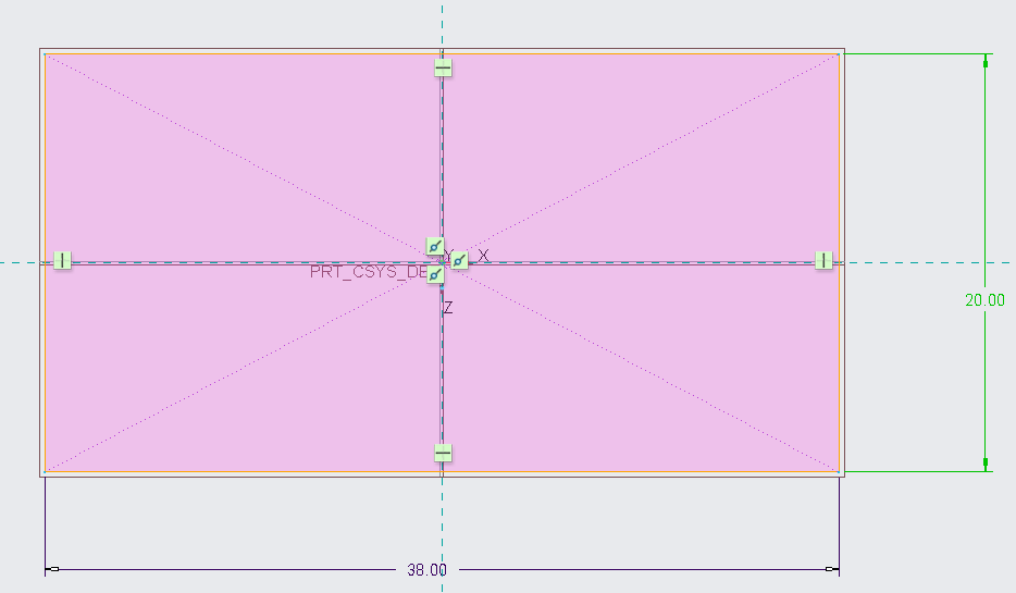
Click on the center and then on any other point. After that press Middle Mouse Button to deselect the rectangle tool.
Give the dimensions to the rectangle as shown. The dimensions can be given by double clicking on the measurement.
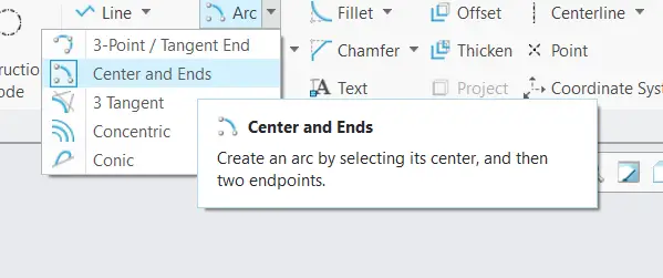
It is important to keep in mind that we are following the top view for this sketch, now we are going to draw the circular areas of the drawing. To do this, select Center and Ends arc from the top.
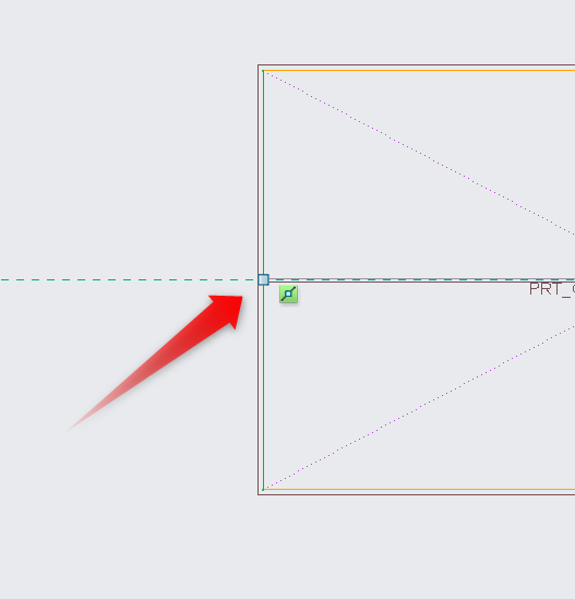
Click on the center of the line along the axis, this would be the center of the arc.
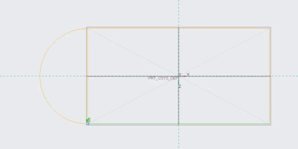
Select the corners of the rectangle to draw the arc as shown.Press the Middle Mouse Button to deselect the command. The radius of the arc will be 10mm. We can change the distance by double clicking the dimension.
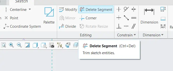
Click Delete Segment from above, it will be used to trim the edges that are not needed.
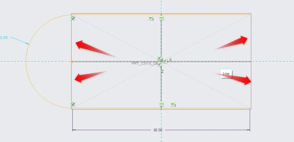
We will be deleting unnecessary segments as shown above. Just click on the segments to delete them. It is important to remember that it is necessary to make a closed geometry in a sketch.
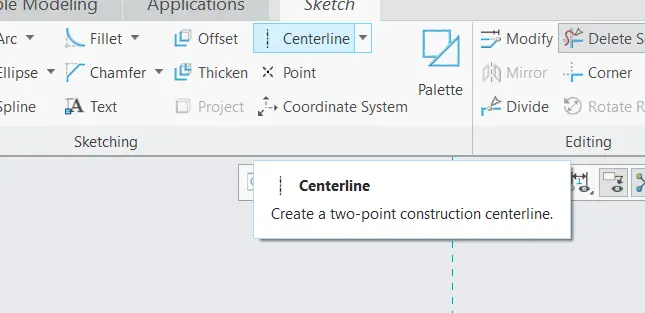
We have to mirror the arc to the other side of the sketch, we can also draw the arc, but this method is much more convenient. To mirror, we first have to draw the centerline. click on the centerline tool as shown above.
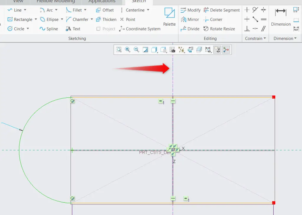
Draw the centerline by clicking any two points on the vertical axis.
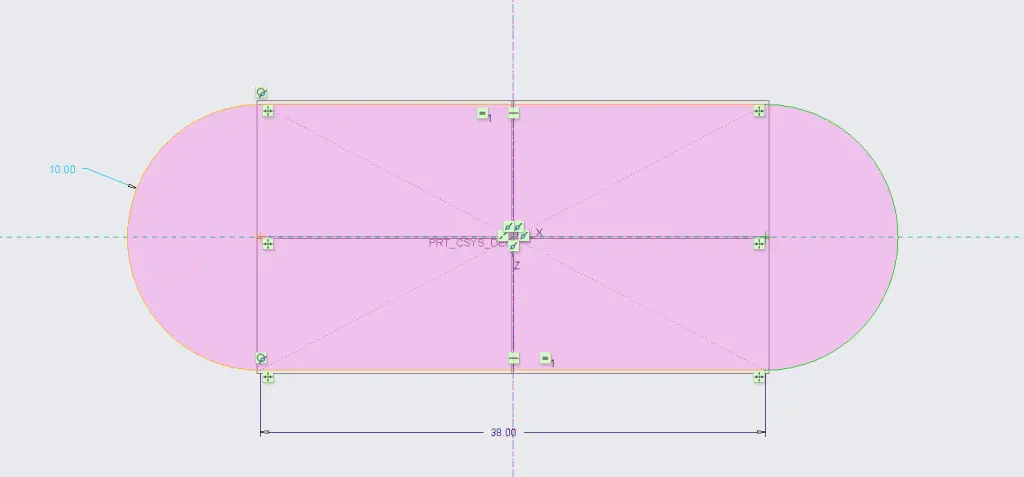
Select the drawn arc, then click on Mirror tool from above and then click on the centerline that you just drew. This will mirror the arc to the other side. The result is shown in the above image.
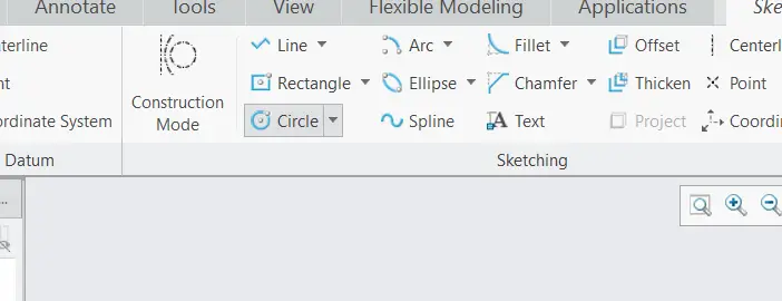
We now have a closed geometry. We need to add holes to our sketch, to do that, we can select the circle tool as shown above.
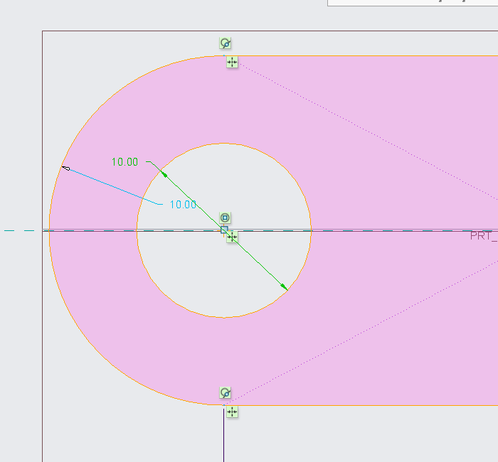
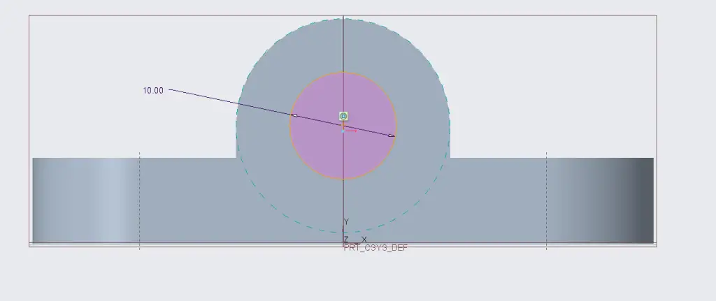
Click on the center of the the arc and draw the circle, press Middle Mouse Button to deselect the tool after drawing the circle, Change the diameter of the circle to 10 mm by double clicking on the dimension shown.
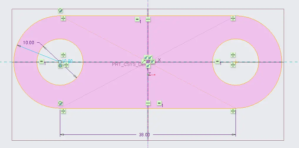
Mirror the hole to the other side of the sketch the same way we did with the arc.
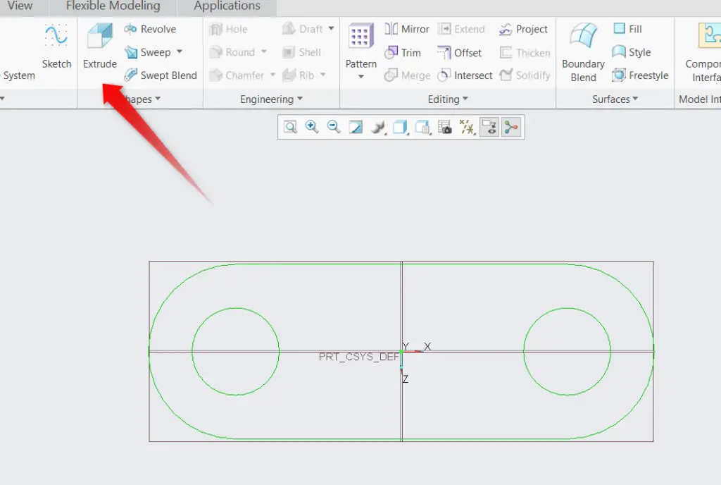
Click the tick sign to confirm the sketch, the sketch is now complete, In the model tab, click the extrude command to extrude.
Note that the top view of the drawing is now complete we will be following the front view from now. But it is necessary to remember that we will need help from the top view also so that the dimensions of the model is like that of the drawing.
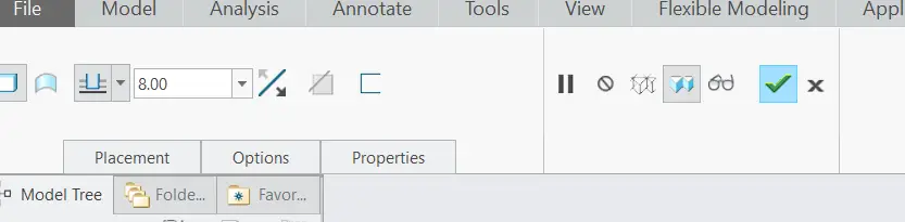
Extrude 8 mm as shown in the image above. Click the tick to confirm.
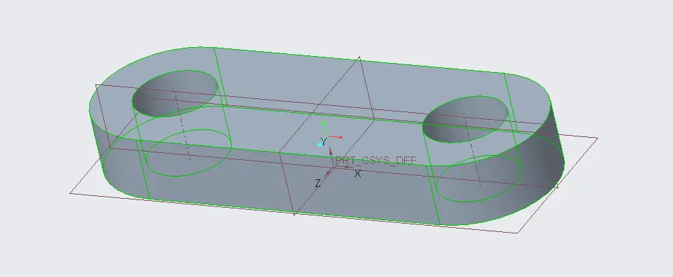
Our part will look like this if all the steps are followed.
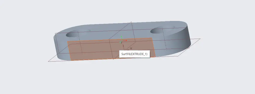
Our geometry isn’t complete, we need to complete the front view, to do this, click on the front surface of the model as shown in above image and click Sketch. Click sketch view from the top bar to orient the view.
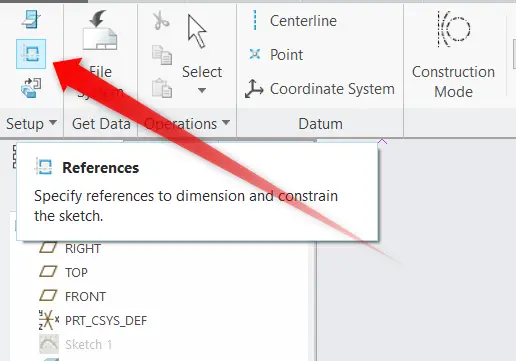
Now click References in the top left corner, References add lines that are not the part of a sketch.
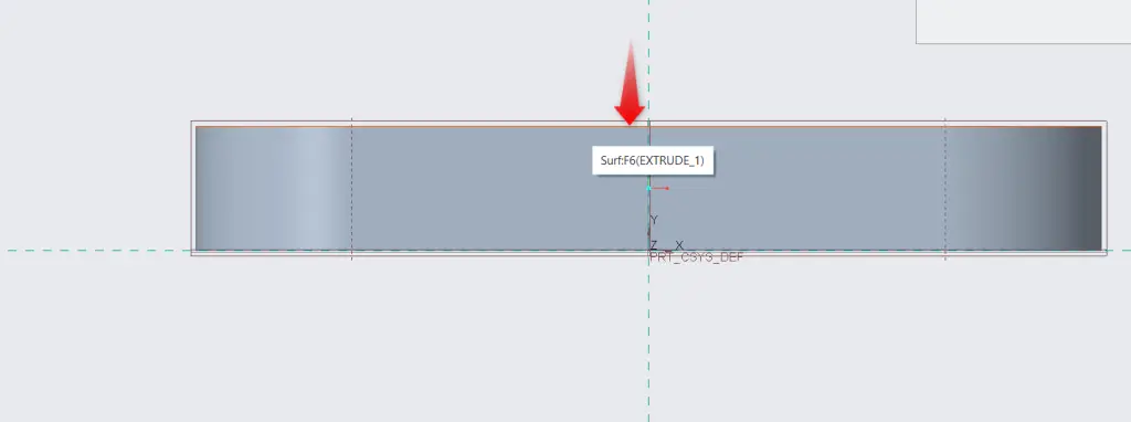
Click on the top edge of the model. A dashed line will appear, now we can sketch exactly on that dashed line.
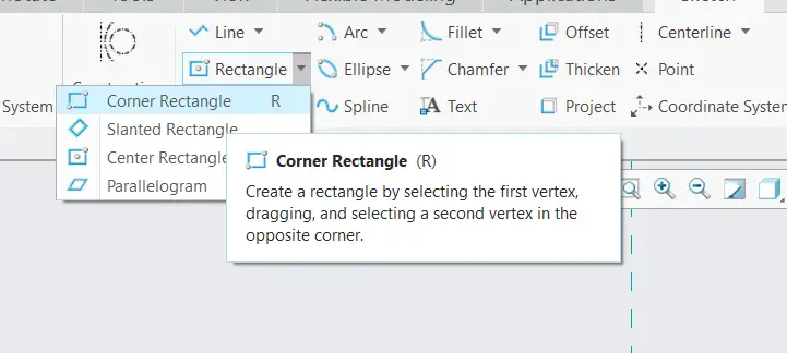
Select Corner Rectangle from Sketch tab. Click Middle Mouse Button to deselect the command.
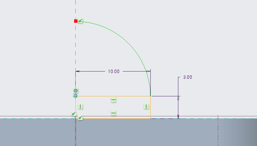
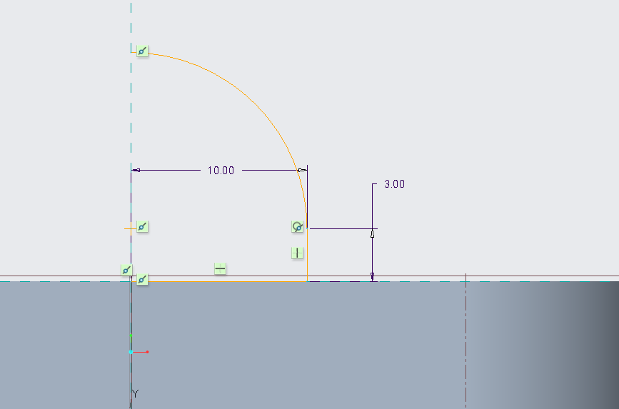
Give the dimensions to the rectangle as shown in above image. Select Arc command from the sketch tab, the rectangle corner along the vertical axis can be chosen as the center of the arc, and then draw the arc from the other rectangle corner to the Vertical axis as shown in image above.
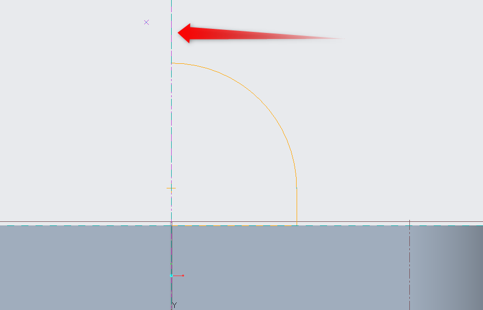
Select Delete Segment and trim the unnecessary segments as shown in image above.
Draw the centerline on the Vertical axis as shown. And mirror the sketch on the other side of the centerline, this way our geometry would be complete, click the tick sin to confirm. After that click Extrude.
Extrude the sketch 20 mm and click tick sign to confirm.
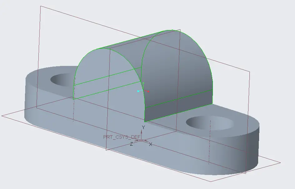
The result will look like the image shown above.
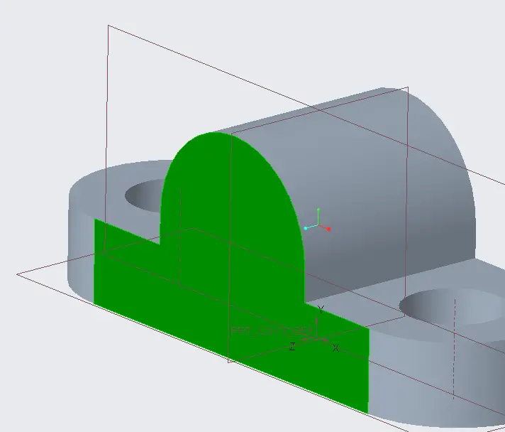
We need to draw a hole in the model. So, we select the front surface of the model and click Sketch.
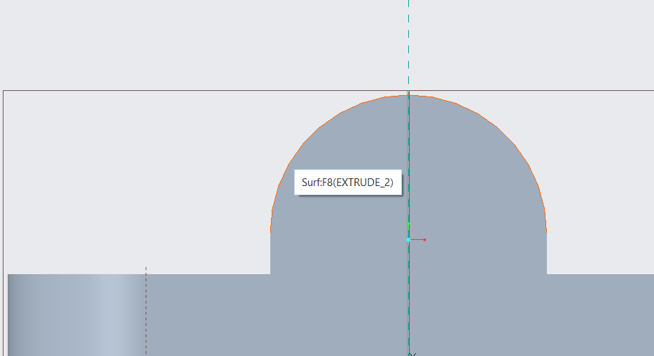
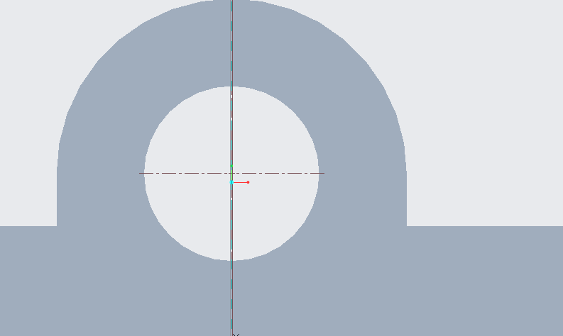
Select References on the top left corner in the sketch tab. Click the circular surface of the model to get the dashed lines and the center of the arc.
Draw the circle on the center of the arc and the diameter should be 10 mm. Click tick to confirm the sketch. And then click extrude
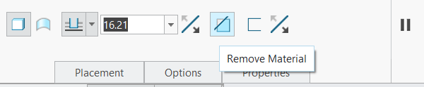
Select the remove material option in the extrude tab. When we extrude inside an object, we need to cut material for extruding, So that’s why this is selected while extruding inside.
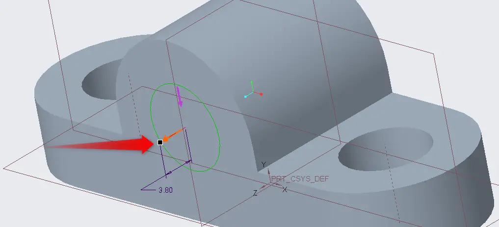
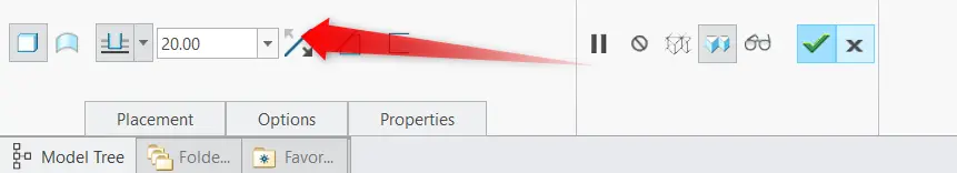
Select rectangle next to arrow and move it towards the model.
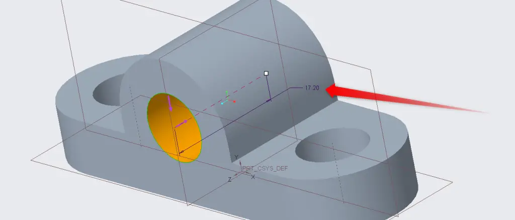
Double click on the dimension to change the length of extrusion.
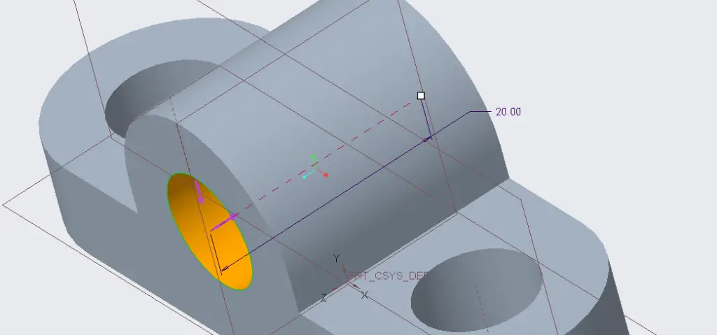
The length of extrude must be 20 mm.
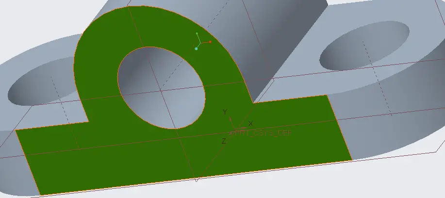
Click on the front surface of the model and click Sketch.
Select References. Draw two circles.
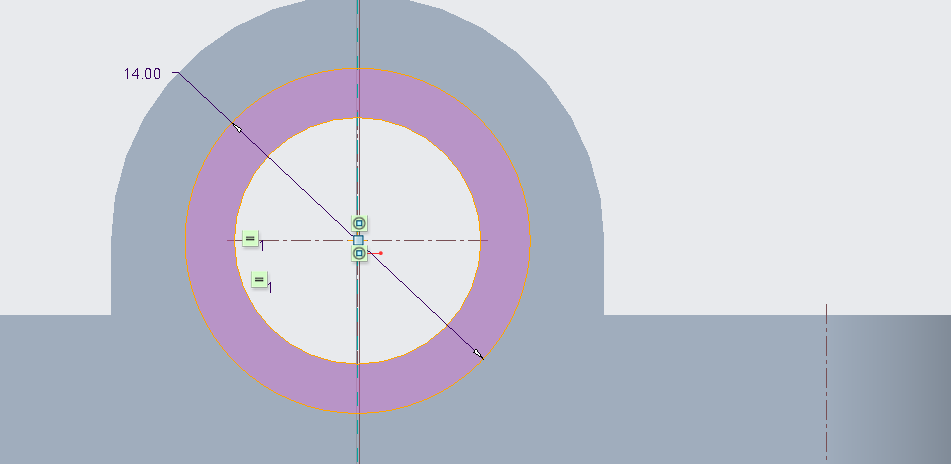
The diameter of one circle should be 10 mm and the other should be 14 mm. The result is shown above.
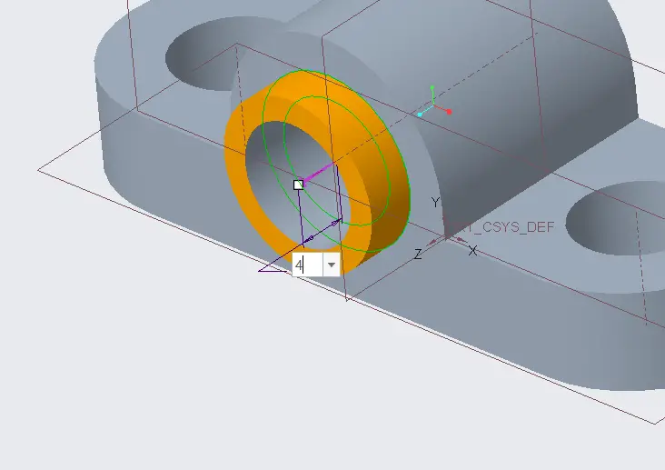
Confirm the sketch, click extrude and extrude length should be 4 mm.
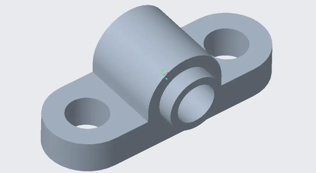
This is the final result.