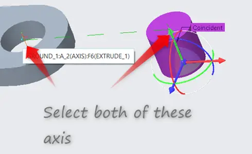
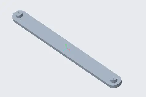
The parts that we have made are circular, circular parts have an axis.
In this case, we select both of the axis, they become coincident. And now this part would rotate about the axis that have been combined.
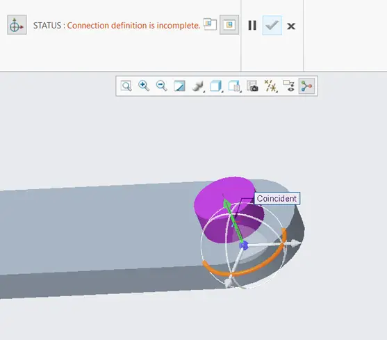
The connection definition is incomplete. Because the part is still able to move in the axial direction, So, we are going to stop it from moving in the axial direction.
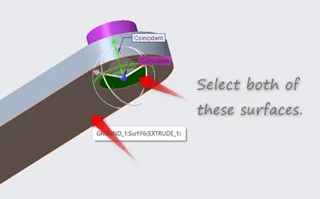
Now, select the bottom surface of the joint and the bottom surface of the ground. By doing this, we have constrained the joint to have the coincident surfaces. Now the joint part will not move.
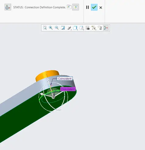
Now, as we can see the status definition is complete, we can click the tick option to confirm the assembly.
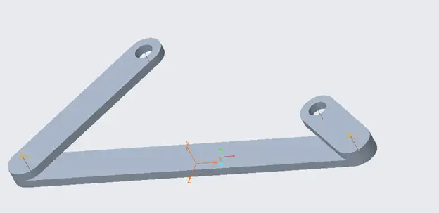
Now add another joint, and assemble on the other side of the ground link the same way the first joint, was assembled. The assembly would look like the figure shown above.
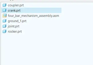
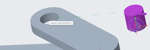
Now we add crank link from assembly.
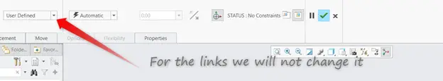
In the component placement, we do not change the “User Defined” or “Automatic” constraints, rather we attach the part to the assembly manually.
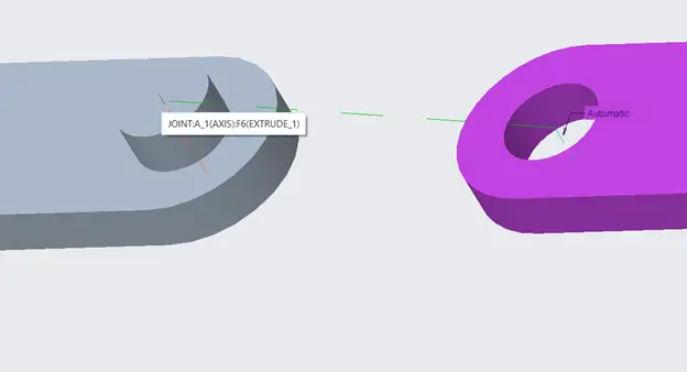
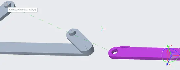
After the crank has been imported, we click the axis of crank and then click the axis of the ground from any of the two sides.
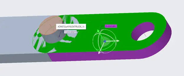
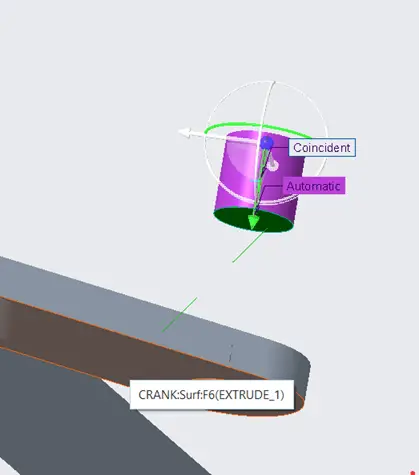
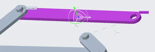
The result would look like something as shown above. Now we have to constrain the surface of the crank, to do this, click the top surface of the joint and the top surface of the crank.
Note that the constraint should coincident, it should not be distance.
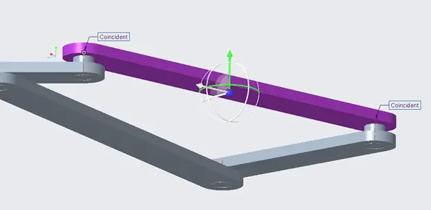
Now, we assemble rocker, the rocker can be assembled to the other side of the ground linkage. The rocker would be assembled the same way crank was assembled.
Now, rocker and crank have been assembled.
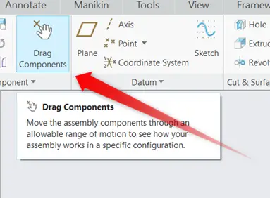
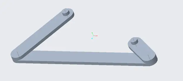
Now from the model tab, click Drag Components and then click on rocker or crank. They should rotate around their respective axis.
In the figure above, we have shown that how rocker and crank can be rotated with Drag Components tool.
Now, we have to assemble joints with rocker and crank on their free sides.
Import the joint by clicking assemble, now join the axis of the joint with free axis of the crank as shown above.
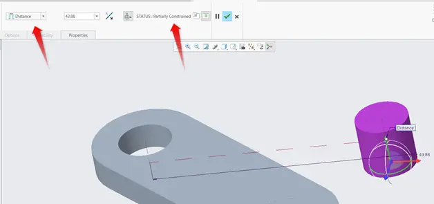
As shown above, the constraint shows distance, we have to change it to coincident. The status is partially constrained, it means that it still has some degree of freedom.
In our case, to constrain the joint, the bottom surface of the joint must coincident with bottom surface of the crank. To do this, we click the bottom surface of the crank and the bottom surface of the joint. Now the status should change to fully constrained.
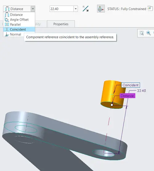
When we select the surfaces, the constraint would be “distance”. Change it to coincident. Distance means there would be distance between the two surfaces. Coincident means there would be no distance between them.
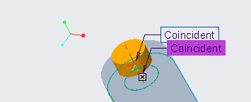
The result would be something like this.
Now the same way, add a joint to the free end of the rocker.
Now we have to add coupler. Go to Assemble, and import coupler. The coupler can be assembled the same way, we did with the crank and rocker, but we have to remember that coupler has two free ends. One will be assembled with the crank and other will assembled with the rocker.
In the component displacement tab, join one axis with axis of the rocker and the other with crank.
Both of the axis must be joined.
The surfaces must be coincident, to do this, select the bottom surface of the coupler and top surface of the crank or rocker.
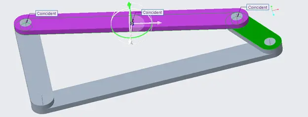
The final result would look like something like the figure shown above. Now if we use Drag Components, we can move the four bar mechanism.